


1.0 Introduction to fiber optic (outdoor)
The exponential growth of data-intensive services, including 5G wireless, cloud computing, and the Internet of Things (IoT), has placed unprecedented demand on the underlying communications infrastructure. Fiber-optic cable, with its high bandwidth and low attenuation, is the primary medium for high-speed data transmission. Outdoor fiber-optic cables, specifically those designed for Outside Plant (OSP) environments, are critical links that connect cities, data centers, and communities. Unlike cables in controlled indoor settings, OSP cables must endure a wide array of environmental and mechanical stresses, from extreme temperatures and moisture ingress to tensile loads during installation and the threat of rodent damage.
1.1 The Role of Outdoor Fiber Optic Cable in Modern Telecommunications
OSP fiber optic cables are the workhorses of the telecommunications industry, forming long-haul, metropolitan, and access networks. Their design must balance the need to protect the delicate optical fibers within while facilitating efficient installation and long-term reliability over decades of service. The selection of an appropriate OSP cable is a critical engineering decision that impacts network performance, deployment cost, and operational longevity. Factors such as fiber count, installation environment (aerial, buried, or duct), and required mechanical durability dictate the specific cable construction. Innovations in cable design, such as high-density ribbon cables and gel-free water-blocking technologies, have enabled network operators to deploy more capacity in limited spaces, reduce installation time, and lower total cost of ownership (Corning, n.d.).
1.2 Scope and Objectives of the Article
This article aims to provide a detailed technical overview of modern outdoor fiber optic cables. The primary objectives are to:
- Elucidate the fundamental construction and material components of OSP cables.
- Differentiate between common OSP cable types and their respective applications.
- Define and quantify the critical mechanical and environmental performance specifications.
- Analyze the technologies used for environmental protection, particularly against moisture.
- Describe standard installation methodologies and best practices.
- Summarize the key regulatory and testing standards that govern OSP cable performance.
The information presented is synthesized from technical datasheets, industry white papers, and standard recommended procedures to serve as a comprehensive resource for network engineers, planners, and technicians.
2.0 Fundamental Cable Construction
An outdoor fiber-optic cable is a multi-layer system designed to protect the optical fibers from mechanical and environmental hazards throughout its service life. While designs vary, most OSP cables share a common set of core components.
2.1 Core Components of an Outdoor Fiber Optic Cable
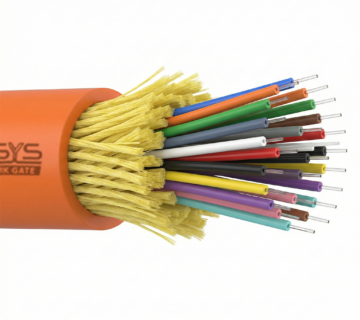
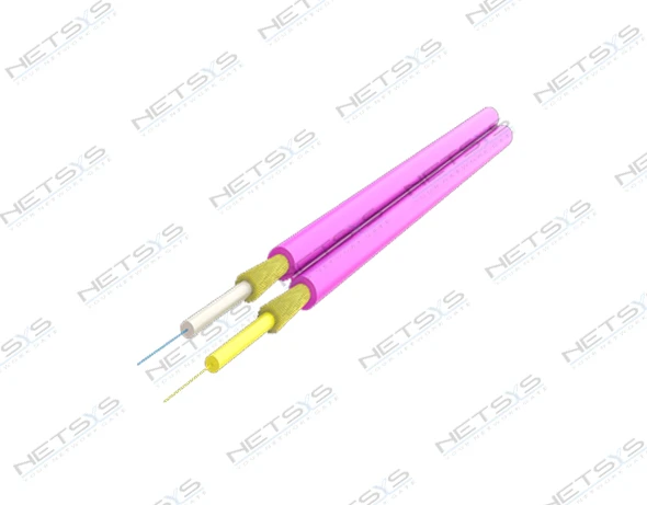
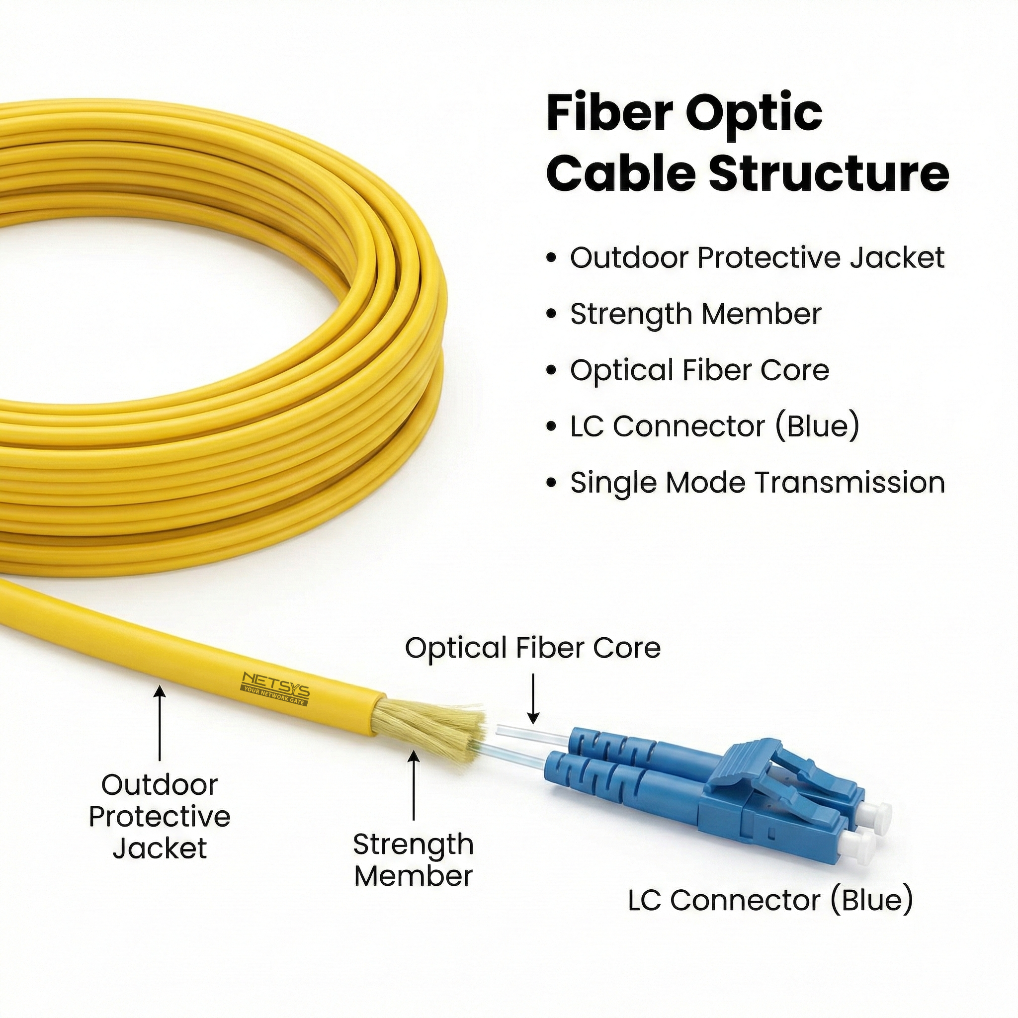
A typical loose tube outdoor fiber cable, as illustrated in Figure 1, consists of several distinct layers, each serving a specific protective function.
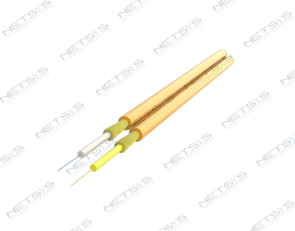
- Optical Fibers: The core data-carrying element, typically made of glass. Each fiber consists of a core, cladding, and a primary coating (250µm diameter) for basic protection.
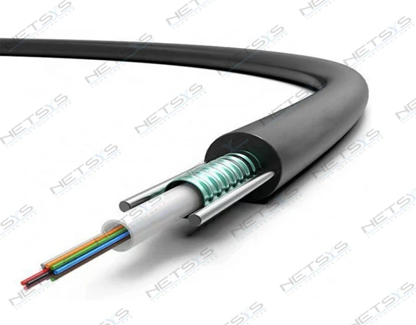
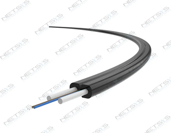
- Buffer Tubes: Plastic tubes that house the optical fibers. In OSP cables, a “loose tube” design is common, where fibers are placed within a gel-filled or dry, water-swellable tube. This design isolates fibers from external mechanical stresses, such as tension and temperature-induced contraction/expansion.
- Strength Members: These components provide tensile strength to the cable, protecting the fibers from being stretched during installation and over their lifetime. They can include a central strength member (CSM), often a glass-reinforced plastic (GRP) or steel wire, and peripheral strength elements like aramid yarns or flexible fiberglass rods.
- Water-Blocking Elements: Essential for preventing moisture from migrating along the cable, which can degrade fiber performance or cause damage in freezing conditions. This is achieved using water-blocking gels, tapes, or yarns that swell upon contact with water.
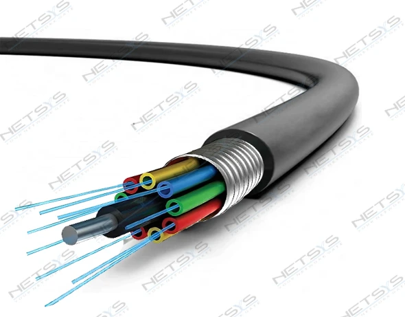
- Armoring Layer: An optional but often critical layer for direct-buried cables. It typically consists of a corrugated steel tape that provides high crush resistance and protection against rodent attacks.
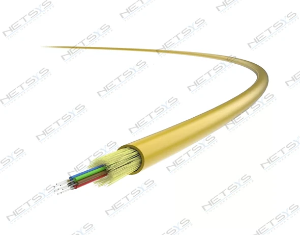
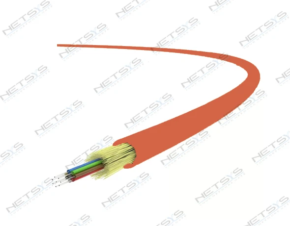
- Outer Jacket: The final protective layer, typically made from a rugged, weather-resistant material like Polyethylene (PE). The jacket shields the internal components from UV radiation, abrasion, and moisture.
2.2 Optical Fiber Types in OSP Applications
While multimode fiber (MMF) is used for short-distance applications, single-mode fiber (SMF) is the standard for OSP networks due to its low attenuation and high bandwidth, enabling long-distance transmission. The most common types specified for OSP use are G. 652. D and G. 657. A1 fibers.
- G.652.D: Known as standard single-mode fiber, it is optimized for operation at 1310 nm but is also usable at 1550 nm. It is the most widely deployed fiber type globally.
- G.657.A1: A bend-insensitive single-mode fiber. It is compatible with G.652.D but offers a significantly smaller minimum bend radius, making it advantageous for high-density installations and drop cables where tight bends are common.
Typical attenuation for OSP single-mode fiber is around 0.35-0.4 dB/km at 1310 nm and 0.21-0.25 dB/km at 1550 nm (fiberopticpatch-cord.com, n.d.; BlackBox, n.d.).
3.0 Key Types of Outdoor Fiber Optic Cables
Outdoor fiber cables are engineered in various configurations to suit different installation environments and network requirements.
3.1 Loose Tube Cables
The stranded loose tube design is the most prevalent for OSP trunk and feeder applications. It involves multiple buffer tubes, each containing several fibers, stranded around a central strength member. This construction provides excellent mechanical and environmental protection, isolating the fibers from external forces. Fiber counts in these cables can range from a few dozen to over 864.
3.2 Ribbon Cables
Ribbon cables offer the highest fiber density available for OSP applications. In this design, individual fibers (typically 12) are bonded together in a flat ribbon. Multiple ribbons are then stacked within the buffer tubes. This architecture allows for significantly higher fiber counts in a given cable diameter compared to loose tube designs (Corning, n.d.). A major advantage of ribbon cable is the efficiency of splicing; a 12-fiber ribbon can be spliced in roughly the same amount of time as a single loose fiber, representing an 80% reduction in splicing time. This dramatically speeds up network deployment and restoration efforts.
3.3 Armored Cables
For direct burial applications where the cable is placed directly in the ground without a conduit, armored cables are essential. They feature a metallic layer, usually of corrugated steel tape, situated beneath the outer jacket. This armor provides robust protection against crushing forces from soil and rocks, as well as providing a formidable barrier against gnawing rodents, a common cause of cable failure in rural areas. Some designs may feature a double jacket with the armor sandwiched between two layers of PE for enhanced protection.
3.4 Aerial Cables
Aerial cables are designed for installation on utility poles. There are three primary types (STL, 2023):
- Lashed Aerial Cable: A standard outdoor cable is lashed to a separate steel messenger strand that is tensioned between poles. The messenger strand bears the mechanical load, keeping the optical cable in a low-stress state.
- Figure-8 Cable: This design integrates the cable and messenger strand into a single unit with a cross-section resembling the number “8”. The upper portion contains the tensioned steel messenger, while the lower portion contains the optical fibers. This simplifies installation as only one cable needs to be deployed.
- All-Dielectric Self-Supporting (ADSS) Cable: ADSS cables are designed to support their own weight and environmental loads without a metallic messenger. They are reinforced with high-tensile strength aramid yarns. Being all-dielectric, they can be safely installed near high-voltage power lines, making them popular for deployment on power utility infrastructure.
4.0 Critical Performance Specifications and Mechanical Properties
The ability of an OSP cable to withstand mechanical stresses during and after installation is defined by a set of standardized performance specifications. These values are determined through rigorous testing procedures defined by standards like the IEC 60794 series and Telcordia GR-20.
4.1 Tensile Strength (Tensile Load)
Tensile strength indicates the maximum pulling force a cable can withstand without damaging the optical fibers. Specifications are typically given for two conditions:
- Short-Term (Installation): The maximum load the cable can endure for a short period during installation (e.g., pulling through conduit or plowing). This value can be as high as 4488 N (1009 lbf) for robust loose tube cables.
- Long-Term (Operational): The maximum sustained load the cable can handle once installed, accounting for factors like cable weight in aerial spans and residual ground stress. This is a lower value, such as 1481 N (333 lbf).
4.2 Crush and Impact Resistance
Crush resistance (or compression) measures the cable’s ability to withstand a steady compressive force without an increase in fiber attenuation. It is critical for direct-buried cables. Values are expressed in Newtons per unit length, such as 22 N/mm or 2000 N/10 cm. Armored cables offer significantly higher crush resistance, with some rated for 1800 N/cm or more.
Impact resistance measures the cable’s ability to withstand a sudden, localized impact, simulating events like a rock strike. It is tested by dropping a specified weight from a certain height onto the cable (FOTP-25 / IEC 60794-1 E4)
4.3 Bending Radius
This specifies the tightest radius a cable can be bent without causing damage or long-term performance degradation. Exceeding this radius can induce stress on the optical fibers, leading to attenuation or even breakage. Two values are provided:
- Dynamic (Loaded): The minimum bend radius during installation when the cable is under tensile load. This is the larger of the two values, often specified as 20 or 25 times the outer cable diameter (OD)
- Static (Unloaded): The minimum bend radius after installation when the cable is at rest. This is a smaller value, typically 10 or 15 times the OD.
4.4 Torsion and Flex Resistance
Torsion (Twist) resistance evaluates the cable’s ability to withstand twisting along its longitudinal axis, which can occur during installation. The test typically involves a set number of cycles (e.g., 10 cycles) per the FOTP-85 test method. Flex resistance measures the cable’s durability against repeated bending at a specific point, a key factor for cables in dynamic applications .
4.5 Vertical Rise and Cable Weight
For vertical installations in buildings or on towers, the maximum unsupported vertical rise is a critical parameter. It is determined by the cable’s tensile strength and its weight per unit length (kg/km or lb/kft). If the vertical rise is too long, the cable’s own weight can create excessive tensile load on the upper portion. For example, a cable weighing 315 kg/km (211.67 lb/kft) with a long-term tensile load of 1481 N has a theoretical maximum vertical rise limited by these factors
| Specification | Value | Test Method / Standard |
|---|---|---|
| Total Fiber Count | 864 | – |
| Cable Type | Ribbon loose tube, non-armored | – |
| Diameter Over Jacket | 21 mm (0.827 in) | – |
| Cable Weight | 315 kg/km (211.67 lb/kft) | – |
| Tensile Load, Short Term | 4488 N (1008.9 lbf) | FOTP-33 / IEC 60794-1 E1 |
| Tensile Load, Long Term | 1481 N (332.9 lbf) | FOTP-33 / IEC 60794-1 E1 |
| Compression (Crush) | 22 N/mm (125.6 lbf/in) | FOTP-41 / IEC 60794-1 E3 |
| Minimum Bend Radius | 314 mm (12.362 in) | – |
| Operating Temperature | -40 °C to +70 °C (-40 °F to +158 °F) | FOTP-3 / IEC 60794-1 F1 |
| Installation Temperature | -30 °C to +60 °C (-22 °F to +140 °F) | – |
| Storage Temperature | -40 °C to +75 °C (-40 °F to +167 °F) | – |
5.0 Environmental Protection and Material Science
The long-term reliability of an OSP cable is heavily dependent on its ability to resist environmental threats, primarily moisture and temperature fluctuations.
5.1 Water Ingress Protection: Gel-Filled vs. Gel-Free (Water-Swellable Tapes)
Preventing water from entering and migrating through a cable is paramount. Two primary technologies are used:
- Gel-Filled Tubes: The traditional method involves filling the buffer tubes with a sticky, water-resistant gel. This gel physically blocks water from entering the tube and reaching the fibers (Coats, n.d.). While effective, the gel is messy to clean during splicing, adding time and labor costs (Corning, n.d.).
- Gel-Free (Dry) Technology: Modern cables increasingly use water-swellable (or super-absorbent) materials. These are incorporated as tapes wrapped around the cable core or yarns within the buffer tubes (STL, 2023). When these materials come into contact with moisture, they rapidly absorb it and swell to form a gel-like plug, effectively blocking further water migration (Pesto Chem, n.d.). This “dry” design is much cleaner and faster for cable preparation and splicing, reducing installation costs. Water-blocking tapes can expand by up to 400% and absorb 50% of their weight in water (Pesto Chem, n.d.).
5.2 Outer Jacket Materials
The outer jacket is the first line of defense. The choice of material depends on the application’s specific requirements for durability, flexibility, and fire safety.
| Material | Key Characteristics | Typical Application |
|---|---|---|
| Polyethylene (PE) | Excellent moisture and weather resistance, high durability, excellent UV resistance (when stabilized). | The standard for dedicated outdoor cables (aerial, direct burial, duct) (Omnicable, n.d.; l-com.com, n.d.). |
| Low Smoke Zero Halogen (LSZH) | Emits limited smoke and no toxic halogens when burned. Less rugged than PE. | Indoor/Outdoor applications where the cable transitions from outside into a building, meeting indoor fire safety codes (lszh-cable.com, n.d.). |
| Polyvinyl Chloride (PVC) | Flexible and low-cost. Generally not as rugged or weather-resistant as PE. | Less common for true OSP, but used in some indoor/outdoor patch cords (Sanspot, n.d.). |
| Thermoplastic Polyurethane (TPU) | Very high flexibility and abrasion resistance. | Specialty outdoor applications requiring high durability and repeated flexing, such as industrial or military field cables (Sanspot, n.d.). |
5.3 Operating, Installation, and Storage Temperature Ranges
OSP cables are rated for three distinct temperature ranges. A typical specification is an operating range of -40°C to +70°C, an installation range of -30°C to +60°C, and a storage range of -40°C to +75°C (CommScope, n.d.-a). The installation range is narrower because extreme cold can make cable materials brittle and susceptible to damage during handling and pulling.
5.4 UV and Rodent Resistance
For aerial cables, the jacket must be stabilized to resist degradation from long-term exposure to ultraviolet (UV) sunlight (CommScope, n.d.-a). Rodent resistance is primarily achieved through the use of metallic armor, as standard PE jackets can be chewed through by animals like gophers and squirrels (fibercablesdirect.com, n.d.).
6.0 Installation Standards and Methodologies
Proper installation is crucial to ensure the long-term performance of OSP fiber optic cable. The methods vary significantly depending on whether the cable is buried, installed on poles, or pulled through conduit.
6.1 Direct Burial Installation
Direct burial involves placing a suitably armored cable directly into the earth. This method is common for long-haul and distribution routes where poles are not available or desired.
6.1.1 Trenching
In this method, a trench is excavated using a backhoe or trencher, the cable is carefully laid at the bottom, and the trench is backfilled. The trench bottom must be free of rocks or sharp debris that could damage the cable. If the soil is rocky, a layer of sand or fine soil should be laid as bedding (OFS, 2018). The cable should be paid off the reel directly into the trench, not pulled along the trench bottom, to avoid jacket abrasion (OFS, 2018).
6.1.2 Plowing
Cable plowing is a faster and more efficient method for long, open routes. A specialized plow with a feed chute creates a slit in the ground and simultaneously inserts the cable at the desired depth. A “ripping pass” without the cable is recommended first to clear the path of obstructions. The prime mover (tractor) must have sufficient horsepower for the soil conditions and burial depth (OFS, 2018). Under no circumstances should the plow be backed up with cable in the chute, as this can cause sharp bends and damage the cable (OFS, 2018).
6.1.3 Recommended Burial Depths
Minimum burial depths are specified to protect the cable from surface activities. Typical recommendations are (OFS, 2018; Unitekfiber, n.d.):
- Trunk/Toll Cables: 30 inches (approx. 0.8 m)
- Feeder/Distribution Cables: 24 inches (approx. 0.6 m)
- Drop Cables: 12 inches (approx. 0.3 m)
Deeper burial is required in agricultural lands to be below the plow line and may also be mandated by authorities for highway or railroad crossings (OFS, 2018).
6.2 Aerial Installation
Aerial installation uses utility poles to suspend the cable above ground. This method is often faster and less expensive than burial, especially in rocky or congested areas.
6.2.1 Lashing Method
The most common method involves stringing a high-strength steel messenger strand between poles and tensioning it to the correct sag. The fiber optic cable is then pulled through temporary rollers (travelers) and permanently attached to the messenger strand using a spinning lashing machine that wraps a wire around both (STL, 2023).
6.2.2 Self-Supporting Methods (ADSS, Figure-8)
ADSS and Figure-8 cables are installed directly, without a separate messenger. They are tensioned to a specific sag and tension value calculated based on span length, temperature, and expected ice and wind loading for the geographic area (STL, 2023). The stationary reel method, where the cable is pulled through blocks on each pole, is often used, especially where obstructions are present.
6.2.3 Installation Tension Management
For all aerial methods, controlling pulling tension is critical. Tensions can approach 600 lbf (approx. 2670 N) during installation (Corning, 2018). Using a capstan assist on the plow or a tension-monitoring pulling system helps prevent exceeding the cable’s maximum rated load (OFS, 2018).
6.3 Duct Installation
In this method, a system of underground conduits (ducts) is installed first. The fiber cable is then either pulled or, more commonly, blown (jetted) through the duct. Duct systems provide excellent protection and allow for easy replacement or addition of future cables. This method is standard in urban environments and for road crossings (OFS, 2018).
7.0 Connectivity and Accessories for Harsh Environments
The reliability of an OSP network also depends on the components used to connect and terminate the cables. These accessories must provide the same level of environmental protection as the cables themselves.
7.1 IP-Rated Connectors and Adapters
For connections made in outdoor enclosures or field-deployable equipment, environmentally sealed connectors are required. IP ratings are used to classify their effectiveness. An IP68 rating signifies that the connector is completely dust-tight and protected against long-term immersion in water. These ruggedized connectors often feature bayonet or threaded locking mechanisms for a secure, vibration-resistant connection.
IP68-rated bulkhead and inline adapters are used to create sealed connections through enclosure walls or to join two ruggedized cables together, ensuring the integrity of the connection point against dust and moisture.
7.2 Cable Glands and Strain Relief
When a cable enters an outdoor enclosure or splice closure, a cable gland is used to seal the entry point. The gland provides a tight seal against environmental elements and also offers strain relief, clamping onto the cable to prevent pulling forces from being transferred to the delicate internal splices or connections.
8.0 Regulatory Compliance and Testing Standards
The performance and reliability of OSP fiber optic cables are governed by a comprehensive set of industry standards. Adherence to these standards ensures that a cable from any manufacturer will meet a baseline level of quality and durability.
8.1 Key Industry Standards
- Telcordia GR-20-CORE: This is one of the most important standards in North America for optical fiber and cable. It outlines the generic requirements for the performance, reliability, and testing of OSP cables, covering a wide range of mechanical and environmental stresses (Experior Labs, n.d.; PhoenixLC, n.d.).
- ANSI/ICEA S-87-640: A standard from the Insulated Cable Engineers Association that specifies requirements for OSP fiber optic cable construction and performance.
- RUS PE-90: A specification from the Rural Utilities Service (part of the USDA) for filled fiber optic cables, often required for government-funded rural broadband projects.
8.2 International Electrotechnical Commission (IEC) Standards
The IEC provides a global framework for standardizing fiber optic cables and test procedures. Key documents include:
- IEC 60794-1 series: Covers general specifications and definitions for fiber optic cables. For example, IEC 60794-1-21 defines mechanical test methods.
- IEC 60794-6: A sectional specification for indoor/outdoor cables, covering cables that are flame-retardant and suitable for both environments.
8.3 Standardized Mechanical Test Procedures (FOTP/IEC Methods)
To ensure consistent and comparable results, specific test procedures are defined for each mechanical property. These are often referred to as Fiber Optic Test Procedures (FOTPs) by the TIA, which are harmonized with the corresponding IEC 60794-1 test methods. Examples include:
- Tensile Performance: FOTP-33 / IEC 60794-1-E1
- Crush/Compression: FOTP-41 / IEC 60794-1-E3
- Impact: FOTP-25 / IEC 60794-1-E4
- Twist/Torsion: FOTP-85 / IEC 60794-1-E7
Cables that meet these standards have been verified to withstand the rigors of their intended OSP application.
9.0 Conclusion
Outdoor fiber optic cable is a highly engineered product designed to maintain the integrity of optical signals in the most demanding environments. The evolution from simple gel-filled loose tube cables to advanced gel-free, high-density ribbon designs reflects the industry’s continuous drive for greater efficiency, higher capacity, and lower deployment costs. The construction of an OSP cable is a sophisticated balance of material science and mechanical engineering, where every component—from the jacket compound to the strength members and water-blocking system—plays a critical role in its long-term viability.
A thorough understanding of the key performance specifications, such as tensile strength, crush resistance, and operating temperature range, is essential for selecting the appropriate cable for a given application, whether it be direct burial, aerial lashing, or duct installation. Adherence to established installation best practices and the use of environmentally sealed connectivity hardware are equally vital to realizing the full performance and lifespan of the cable. By leveraging cables that are designed, tested, and installed in accordance with rigorous industry standards like Telcordia GR-20 and IEC 60794, network operators can build robust, reliable, and future-proof communication infrastructures capable of meeting the world’s growing demand for data.